Questions Related to CNS2018 Poster

Hi Guys,

I’m trying to understand the Learning Relative Landmark Locations Poster but some of the things are not clear to me. So I’d like to ask couple of questions - maybe someone here has the answers.

1, How exactly did this test work - I.e. currently I imagine there was a feature sensor moving randomly across the 16 locations where the features were encoded as SDR and fed to the input layer (and the grid cell layer was driven by both “input layer” and “motor” layer somehow). Correct or not?

2, Grid module drivers - in the section “Network model” there is an overview of the network model. The only thing that is not clear to me is how the grid module is driven. I.e. I see green arrows coming from “input layer” and from “motor” but I’d like to understand how exactly it’s implemented. I’m imagining that what this means is that for a proximal dendrite of a cell in the grid layer half of the synapses have inputs coming from “input layer” and the other half of the synapses has input coming from the “motor” layer. Is this correct or how exactly does this work?
image
image

3, Environments and landmarks - In the “Results” section there is this sentence:

Network trained on 1000 environments, each with 16 locations containing random landmarks from a pool of 5 unique landmarks

On the picture in the poster I see that the environment has 4x4 grid, each field labeled with a letter. But what exactly is meant by random landmark?

4, Displacement layer - could you explain how exactly the displacement layer works (best on an example of a room used in this poster). Here too, if I try to imagine a neuron and it’s proximal dendrite and how the grid cells are projecting onto this dendrite - I’m lost.

I think I rougly get the point of this poster but as I would like to implement this in my own code and play with it a bit, I would like to understand the details. But then again, maybe I don’t understand it at all…

Thank you in advance for your time.

MH

1 Like

1, How exactly did this test work

First, a set of landmarks are generated. These are reused in many locations. In the experiment, they are simply an SDR that will be fed into the Temporal Memory as proximal input.

Then the environments are generated as 4x4 grids with each position in the grid containing a landmark randomly chosen from the pool. The letters in the picture correspond to which landmark is at that position.

2, Grid module drivers

During learning and inference, a traversal of the environment was done by shuffling the set of 16 locations on the environment and moving between them sequentially. The landmark SDR is fed to the Temporal Memory and the movement (like (+2, -1)) was fed to the location layer to perform path integration. Each module independently shifts it’s active cells based on the movement. Modules can have different scales and orientations, which are essentially affine transformations of the movement.

Your drawing indicates that you are interested in the actual neuron model. The ideas in the paper aren’t tied to any specific neuron model but I can describe the closest thing thing to the abstract simulations that I implemented. The neurons can become active in two ways. One is from input layer connections. The other is from path integration based on motor commands. Each would be done via different proximal segments on the neurons. The path integration segments would have connections from another cell in the module plus the motor command. The connections from the input layer would have their own segments.

I’m not trying to push this neuron model, we just don’t have a solid understanding of the connections in EC that perform both path integration and sensory anchoring.

3, Environments and landmarks

Landmarks in these simulations are just SDRs. A set of unique landmarks are generated up front and then environments are created by randomly choosing one of the landmarks for each location. In reality, landmarks are generally complex things with multiple sensory inputs for different parts or perspectives of the animal. We’ve ignored that here and assume that landmarks have a single possible sensory input pattern and is sensed when the animal is in one exact location.

4, Displacement layer

If the location modules are 5x5 (so 25 cells), then the displacement modules also have 25 cells. If you consider the top left location cell, each displacement cell will have a segment that contains connections from the top left location cell plus one of the other cells. Which other cell determines “relative position” that the displacement cell is encoded. That displacement cell will then keep adding segments for each pair of location cells that have the same relative positions (modulo 5). Each displacement cell will have 25 different segments, each with connections from one pair of location cells that are in this relative configuration. E.g. there will be a displacement cell that has a separate segment for each pair of cells in which one cell is directly to the right of the other (relative position of (+1, 0)). A different displacement cell will encode “two to the right”, etc.

What is amazing is that you can use just 25 displacement cells in this case to represent a huge number of potential displacements. The module by itself is thus ambiguous (the “two to the right” displacement cell may also represent “seven to the right”) but when you look at the representations in the entire set of displacement modules you get a very unique displacement code. This does require that the different location modules use different scales and/or orientations though.

In general, we aren’t happy with the neuron models we are using and we know that our binary single-cell-per-module activations don’t match closely with real grid cells that exhibit bumps of activity around a given location. This is a big topic and I think everyone has slightly different opinions about how grid cells really work. But the point of this paper is that regardless of the neuron model, displacement cells provide representations that have nice properties.

I think I covered all of your questions but let me know if I missed something or if you have more.

6 Likes

Hi Scott,

first of all thank you for taking the time to provide this kind of feedback - it really helps me to have this kind of response. I really appreciate your effort, thank you for that!

1, How exactly did this test work

Ok, clear now, thank you. I was confused because in the poster there is this sentence

Network trained on 1000 environments , each with 16 locations
containing random landmarks from a pool of 5 unique landmarks

But the environment itself has landmarks A, B, C, D, E, F, G, I, J - so I didn’t know what’s going on. Now clear.
image

2, Grid module drivers

Your drawing indicates that you are interested in the actual neuron model.

Correct, I was automatically assuming you’re using only HTM/Numenta neuron when you’re performing any experiments. And as I’ve seen this neuron pictured with only one proximal dendrite, I wasn’t sure if you started using more than one prox. dend. or if you’re putting inputs from different layers onto a single dendrite or something else. But now it’s clear.

3, Environment and landmarks
Just SDRs - perfect, got it, thank you.

4, Displacement layer

Clear now, thank you - but thinking about this is leading me to another point/question:

5, Movement through the environment
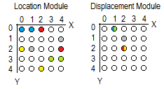
Just to illustrate - one location (=Grid cell) module (left), one displacement module (right) and cells are connected as you described above in the answer to “4, Displacement layer” (I hope I got it right as it sounds simple)

  • I’ve used blue for location (0,0) and for location (1,0), the displacement being (1,0)
  • Same for the green location cells (3,3) and (4,3); the displacement is the same (1,0) - hence the cell (1,0) in the displacement module is marked half blue/half green
  • same with red & yellow cells (and the same resulting red/yellow cell in displ. module)

image

And the question is: The location module from the poster has cells active based on previous AND on current position, correct?

The reason for this question is that if all the above is correct I need to have two locations (whether it is two cells or more biology-like example of a union of two SDRs) active in the location module (so that I can compute the relative location stored in the displacement module). The easiest way I see to achieve this is to simply have previous and current position.

Just to be sure - let’s say we’re in the environment from the poster, at the “D” landmark (0,0) and moving to “F” on (1,0). What happened is that first you’ve initialized the grid cell layer with (0,0) and fed the SDR for “D”, then provided the movement command to move to (1,0) and fed the network the SDR for “F”? Then the displacement layer was able to take union of grid cells from positions (0,0) and (1,0) and activate a cell in the displacement layer?
image

And that’s it. Thank you for your time and effort!

MH

Which cell is activated in the grid cell layer does not relate to where the landmark is in the environment. So in your example, just because “D” is in the (0, 0) position in the environment doesn’t mean that it will activate the (0, 0) position in the location layer. Instead, we first learned each landmark by picking a random position in the location layer to associate it with. This actually involves picking a random cell in each mini-column in the input layer and those cells are associated with the randomly chosen cell in each location layer module.

So in the first step, we sense “D”. Let’s assume that the randomly chosen location cell that is associated with “D” is (2, 1). So when we sense “D” we activate the input layer minicolumns and the cells in those minicolumns that learned “D” will drive the (2, 1) location layer cell to be active.

Then we move to the right and sense F. When we move, we shift the location layer activity based on the motor command and the scale/orientation of the module. For simplicity, let’s say the module in question has the same scale and orientation of the environment, so the activity shifts from (2, 1) to (3, 1). This new cell (3, 1) is now representing our position relative to “D”. Let’s additionally assume that when we learned the “F” landmark that it was associated with (1, 1) in the location layer. So that cell becomes active as well. We now have a union of active cells in the location layer module that consists of (3, 1) and (1, 1). We can activate the displacement that corresponds to (1, 1) - (3, 1) modulo 4.

We continue on by:

  • Moving, shifting all location layer activity in proportion to the motor command
  • Sensing a new feature and activating the location layer representation that we associated it with when we learned it.
  • Activating the displacements for the newly activated location layer cell with each of the location layer cells in the union.
  • If the union of activity in the location layer grows beyond some limit, then we drop off the cells for oldest landmarks to avoid getting too dense activity in the location layer modules.

You can think of the location layer activity as representing our position relative to a recent set of landmarks. The displacement cells are representing the relative positions of pairs of these landmarks in this particular environment.

Hopefully that helps with the remaining parts.

1 Like

Hi Scott,

perfect, now it’s completelly clear. Thank you for the explanation!

MH

1 Like

I wonder how the “inverse” (i.e. inference) of tracking movement/location can fit into this theory…
Suppose I’m in a certain location, based on a certain landmark, what’s the motor command to get to another location ?
Does “imagining” and activating the next location activate the correct displacement cell ? and if so, how is the right motor command calculated ?